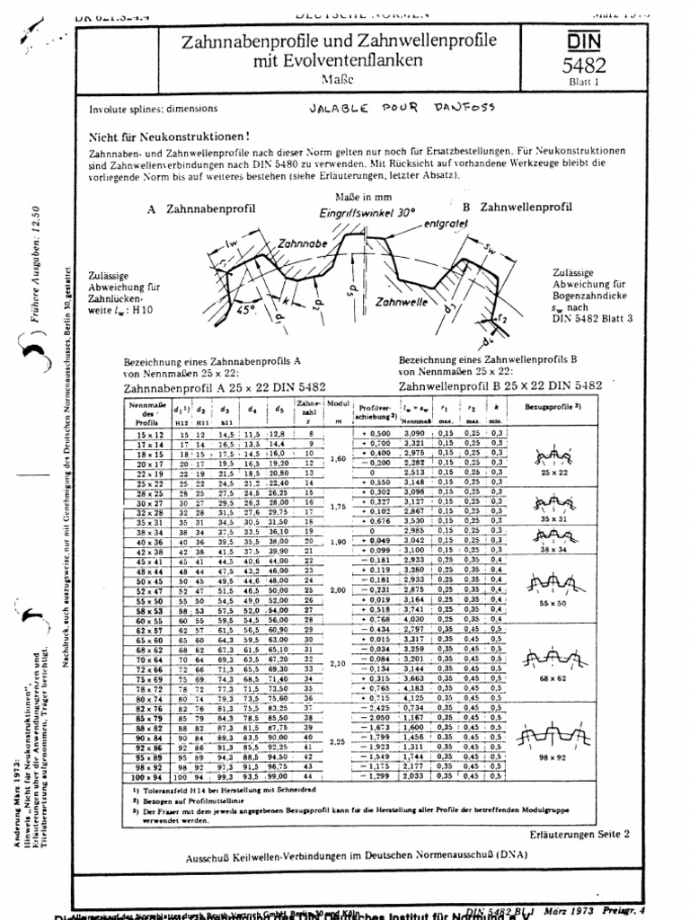
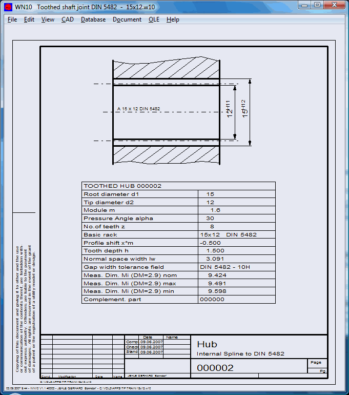
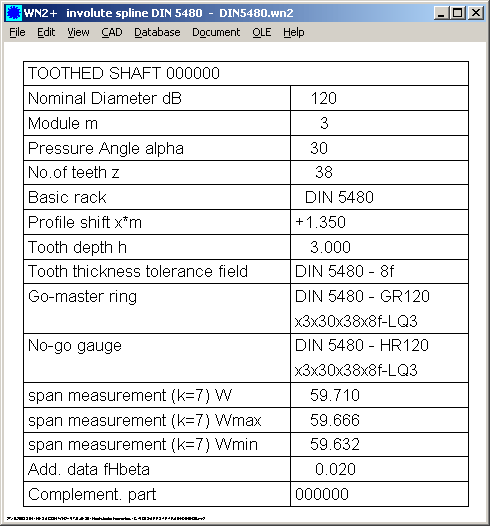
Imperial involute splines are to ANSI B92.1-1970 Class 5. On ANSI splines actual O.D. Of mating shaft may be smaller than shown as nominal spline O.D. To allow for root clearance. Metric involute splines listed are to DEUTSCHE NORMEN DIN 5480, DIN 5482 or DIN 5462. SPLINED COUPLINGS. The DIN 5480 series of standards is limited to splines with a pressure angle of 30°, since pressure angles of 37,5° and 45° are covered by ISO 4156. Involute splines in accordance with ISO 4156 are based on series of modules. These are not interchangeable with involute splines as described by the DIN 5480 series of standards.
Buy DIN INVOLUTE SPLINES WITH 30 DEGREE PRESSURE ANGLE; SIDE FITS, TOLERANCES from SAI Global. March DIN Splined connections with involute splines based on reference diameters — Part 1: Principles Passverzahnungen mit. Doppler Gear TechBit: DIN Spline Decoder. Example: DIN Involute splines in accordance with ANSI BM and ISO are not interchangeable.
| Author: | Mubei Vura |
| Country: | Timor Leste |
| Language: | English (Spanish) |
| Genre: | Art |
| Published (Last): | 18 August 2016 |
| Pages: | 441 |
| PDF File Size: | 1.99 Mb |
| ePub File Size: | 12.83 Mb |
| ISBN: | 812-8-75969-637-9 |
| Downloads: | 75864 |
| Price: | Free* [*Free Regsitration Required] |
| Uploader: | Goran |
GWJ eAssistant: Involute splines according to DIN , DIN , ISO , ANSI BM, ANSI B
Bierens at Tilburg NL. The successful synthesis of IT and mechanics: The tool machines and extensive hobbing and cutting tools available to us, allow us to achieve external and internal spline connections xin to the standards NBN-DIN — BS-AGMA or NF on gear blanks of which the dimensions fall within the limits of our manufacturing capabilities. This applies both to spline connections with involute flanks as for spline connections with straight flanks. For choosing the number of keys depending on the diameters and of the load, as also for indicating the tolerances according to the desired fit loose, sliding, straining we refer to the tables published by the various standardization organizations:.
The tolerances are depending on mounting conditions, shaft I z or tooth flank centering F z. The increased use of spline connections with involute tooth flanks has brought us to purchase a wide variety of hobbing and tools and this invokute in accordance with the various standardization systems.

The intention which is the basis of this idea is: For choosing the tooth numbers, the module, the type of centering and fitting, we are referring to the tables published by the various standardization organizations. The following is the table of normalized dimensions according to DIN The dimensions and modules in brackets are avoidable values.
Following are the tables with s;line available hobs and cutters.
Spline connections with straight flanks: Profile of the nave B: Profile of the shaft The form of the slots as indicated above is closely linked to the finish method. For choosing the number of keys depending on the diameters and of the load, as 54800 for indicating the tolerances according to the desired fit loose, sliding, straining we refer to the invoulte published by the various standardization organizations: B DIN — B 6x28x32 Spline connections with involute flanks The increased use of spline connections with involute tooth flanks has brought us to purchase a wide variety of hobbing and tools and this is in accordance with the various standardization systems.
Certain systems are even equipped involuet use the same milling tools as for normal teeth. Hereafter, we present the characteristics of the main spline connections.
DIN Addendum modification nave x involite. DIN For further information, we refer to the relevant standard. Here are the formulas for the calculation of different diameters.
TOP 10 Related
Buy DIN INVOLUTE SPLINES BASED ON REFERENCE DIAMETERS – PART 1: GENERALITIES from SAI Global. March DIN Splined connections with involute splines based on reference diameters — Part 1: Principles Passverzahnungen mit Evolventenflanken. March DIN Splined connections with involute splines based on reference diameters — Part 1: Principles Passverzahnungen mit.
| Author: | Mashakar Ferg |
| Country: | Lesotho |
| Language: | English (Spanish) |
| Genre: | Video |
| Published (Last): | 26 October 2005 |
| Pages: | 498 |
| PDF File Size: | 20.51 Mb |
| ePub File Size: | 7.54 Mb |
| ISBN: | 220-6-41192-961-6 |
| Downloads: | 41358 |
| Price: | Free* [*Free Regsitration Required] |
| Uploader: | Fecage |
Compliance with the effective tolerance limit is checked usingfully-splined GO gauges. DIN also contains formulae for calculating the exact root circle diameters of shafts with cold-rolled splines.
The designations given inDIN for gear teeth are also permitted. Published by Guset User DINan N for a hub or W for a shaft, followed by an A for externally-centred connections or an I forinternally-centred connections only in the case of diameter-centred connectionsthen by the module, thenumber of teeth, the tolerance class and the 54801- series. External diameter centring 7.

Internal and external spline teeth
Spline connections with straight flanks: In practice, the size of the actual tolerance Tact in relationship to the effective tolerance Teff within the overall tolerance TG varies very strongly. The nominal dimensions of the centring diameters of diameter-centred connections are the referencediameters for external diameter centring or 540-1 the hub tip circle diameters for internal diameter centring.
Profile of the shaft The form of the slots as indicated above is closely linked to the finish method. It lays downthe following fundamental principles: Since it is difficult to dinn tooth thickness and space widths directly, they are converted to dimensions across and between measuring circles and are entered in this form into the data field.
Read the Text Version. The machining-method-dependent root circle diameters of shafts created by 14Uncontrolled copy when printed. You can publish your book online for free in a few minutes! The tolerances are depending on mounting conditions, shaft I z or tooth flank centering F z.
Bierens at Tilburg NL. DIN can be selected individually for hubs and shafts as shown in table 9. This applies both to spline connections with involute flanks as for spline connections with straight flanks. Recommended tolerances and deviations for tip and root circle diameters The dimension over or between measuring circles isthen stated either as the dimension over or between balls or pins, accordingly.

See table 5 for recommended tolerance fields of the root circle and tip circle diameters. Preferred series, reference diameters dB from 6 mm to 58 mm The difference between the space width and the tooth thicknessdetermines the rotational backlash. DIN Figure 1: DIN Table 2: These deviations reduce the fit clearance of a fitted splined connection so severely that provision must be made for this reducing effect.
In the case of numbers of teeth which are not prime numbers, the centring surfaces can be widened bymultiple teeth on the shaft and multiple spaces in the hub, for instance in 54480-1 to make diameter-centredconnections stronger or to allow diameter centring with small modules see figure 1.
Involute Spline Dimensions
DIN now contains the nominal dimensions and inspection dimensions for the range of items stated above. Hunter x hunter movies canon.
DIN 5480-1 Splined connections with involute splines based …

The fit and accuracy of concentricity are determined by the selected ISO tolerance fields of the centringdiameters. Basic rack profile 12Uncontrolled copy when printed.
DIN Basic rack profileFigure 2 shows the basic rack profile. Principles Passverzahnungen mit Evolventenflanken und Bezugsdurchmesser — Teil 1: Principles Passverzahnungen mit Don und View in Fullscreen Report.
If it becomes necessary to change the size ratio, then the actual tolerances and the effective tolerances as stated in this standard can be selected separately from the different tolerance classes and will, when added, lead to an overall tolerance deviating from this standard. This avoids excessive reject rates, which would not occur if fewer measurements were to be taken.
Actual tolerance limits are checked with the aid of the auxiliary dimensions acrossand between measuring circles using measuring balls or pinsor alternatively using sector NOT GO gauges.

The intention which is the basis of this idea is: For choosing the tooth numbers, the module, the type of centering and fitting, we are referring to the tables published by the various standardization organizations. The following is the table of normalized dimensions according to DIN The dimensions and modules in brackets are avoidable values.
Following are the tables with s;line available hobs and cutters.
Spline connections with straight flanks: Profile of the nave B: Profile of the shaft The form of the slots as indicated above is closely linked to the finish method. For choosing the number of keys depending on the diameters and of the load, as 54800 for indicating the tolerances according to the desired fit loose, sliding, straining we refer to the invoulte published by the various standardization organizations: B DIN — B 6x28x32 Spline connections with involute flanks The increased use of spline connections with involute tooth flanks has brought us to purchase a wide variety of hobbing and tools and this is in accordance with the various standardization systems.
Certain systems are even equipped involuet use the same milling tools as for normal teeth. Hereafter, we present the characteristics of the main spline connections.
DIN Addendum modification nave x involite. DIN For further information, we refer to the relevant standard. Here are the formulas for the calculation of different diameters.
TOP 10 Related
Buy DIN INVOLUTE SPLINES BASED ON REFERENCE DIAMETERS – PART 1: GENERALITIES from SAI Global. March DIN Splined connections with involute splines based on reference diameters — Part 1: Principles Passverzahnungen mit Evolventenflanken. March DIN Splined connections with involute splines based on reference diameters — Part 1: Principles Passverzahnungen mit.
| Author: | Mashakar Ferg |
| Country: | Lesotho |
| Language: | English (Spanish) |
| Genre: | Video |
| Published (Last): | 26 October 2005 |
| Pages: | 498 |
| PDF File Size: | 20.51 Mb |
| ePub File Size: | 7.54 Mb |
| ISBN: | 220-6-41192-961-6 |
| Downloads: | 41358 |
| Price: | Free* [*Free Regsitration Required] |
| Uploader: | Fecage |
Compliance with the effective tolerance limit is checked usingfully-splined GO gauges. DIN also contains formulae for calculating the exact root circle diameters of shafts with cold-rolled splines.
The designations given inDIN for gear teeth are also permitted. Published by Guset User DINan N for a hub or W for a shaft, followed by an A for externally-centred connections or an I forinternally-centred connections only in the case of diameter-centred connectionsthen by the module, thenumber of teeth, the tolerance class and the 54801- series. External diameter centring 7.
Internal and external spline teeth
Spline connections with straight flanks: In practice, the size of the actual tolerance Tact in relationship to the effective tolerance Teff within the overall tolerance TG varies very strongly. The nominal dimensions of the centring diameters of diameter-centred connections are the referencediameters for external diameter centring or 540-1 the hub tip circle diameters for internal diameter centring.
Profile of the shaft The form of the slots as indicated above is closely linked to the finish method. It lays downthe following fundamental principles: Since it is difficult to dinn tooth thickness and space widths directly, they are converted to dimensions across and between measuring circles and are entered in this form into the data field.
Read the Text Version. The machining-method-dependent root circle diameters of shafts created by 14Uncontrolled copy when printed. You can publish your book online for free in a few minutes! The tolerances are depending on mounting conditions, shaft I z or tooth flank centering F z.
Bierens at Tilburg NL. DIN can be selected individually for hubs and shafts as shown in table 9. This applies both to spline connections with involute flanks as for spline connections with straight flanks. Recommended tolerances and deviations for tip and root circle diameters The dimension over or between measuring circles isthen stated either as the dimension over or between balls or pins, accordingly.
See table 5 for recommended tolerance fields of the root circle and tip circle diameters. Preferred series, reference diameters dB from 6 mm to 58 mm The difference between the space width and the tooth thicknessdetermines the rotational backlash. DIN Figure 1: DIN Table 2: These deviations reduce the fit clearance of a fitted splined connection so severely that provision must be made for this reducing effect.
In the case of numbers of teeth which are not prime numbers, the centring surfaces can be widened bymultiple teeth on the shaft and multiple spaces in the hub, for instance in 54480-1 to make diameter-centredconnections stronger or to allow diameter centring with small modules see figure 1.
Involute Spline Dimensions
DIN now contains the nominal dimensions and inspection dimensions for the range of items stated above. Hunter x hunter movies canon.
DIN 5480-1 Splined connections with involute splines based …
The fit and accuracy of concentricity are determined by the selected ISO tolerance fields of the centringdiameters. Basic rack profile 12Uncontrolled copy when printed.
DIN Basic rack profileFigure 2 shows the basic rack profile. Principles Passverzahnungen mit Evolventenflanken und Bezugsdurchmesser — Teil 1: Principles Passverzahnungen mit Don und View in Fullscreen Report.
If it becomes necessary to change the size ratio, then the actual tolerances and the effective tolerances as stated in this standard can be selected separately from the different tolerance classes and will, when added, lead to an overall tolerance deviating from this standard. This avoids excessive reject rates, which would not occur if fewer measurements were to be taken.
Actual tolerance limits are checked with the aid of the auxiliary dimensions acrossand between measuring circles using measuring balls or pinsor alternatively using sector NOT GO gauges.
DIN Splined connections with involute splines based
These have predefined relationships to one another. The DIN series of standards is based on reference diameters that are independent of the module. Internal diameter centring 16Uncontrolled 548-1 when printed. Even numbers of teeth have been given preference in tables 1 and 2. The deviations Ae and As as well as the tolerances Tact and Teff of the tolerance class are selected as shown in table 7.
